Lantern Pad and Stool Detail Drawing Fills with Base Plate Sizes
Description
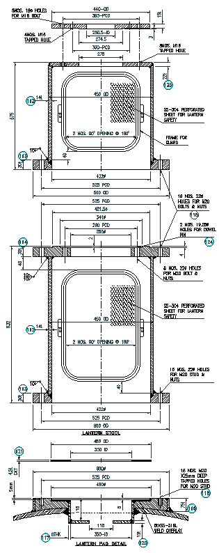
This AutoCAD drawing presents a detailed lantern pad and stool detail design prepared for structural and foundation-level coordination. The drawing clearly illustrates the lantern pad layout, reinforced concrete stool configuration, base plate positioning, anchor bolt alignment, and centerline references. Precise dimensions for pad width, stool height, opening radius, plate thickness, and bolt spacing are shown to support accurate site execution. Sectional views, plan views, and elevation references are provided to help understand load transfer from the equipment or column base to the foundation. The lantern pad detail includes dimensional annotations, edge offsets, and fixing locations essential for civil and structural detailing. Keywords included lantern pad detail, stool detail, and lantern pad drawing.
The stool detail further defines base plate seating, anchor bolt holes, nut and washer locations, and reinforcement clearances. Measurement data is clearly marked to assist in setting out, shuttering, and concreting works on site. This lantern pad and stool design drawing is suitable for engineers and designers working on industrial, utility, or infrastructure foundations where equipment mounting accuracy is critical. The structured layout, readable scaling, and construction-ready detailing make the drawing useful for planning, checking, and execution stages. Keywords included lantern pad and stool design, structural lantern pad detail, and lantern pad stool foundation detail.

Uploaded by:
Liam
White